THz Scanning Fabry-Perot Interferometer
| Download THz Scanning Fabry-Perot Interferometer Datasheet (PDF, 424 KB) |
Terahertz scanning Fabry-Perot interferometer (TSFPI) is designed for measuring wavelength and intensity of narrowband THz radiation. TSFPI may be used with pulsed as well as continuous sources of narrowband THz radiation. 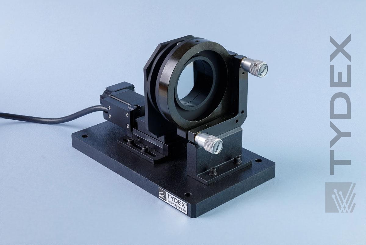
TSFPI is comprised of two semi-transparent parallel silicon mirrors, one of those is mounted on a motor-driven linear actuator. Measuring of THz radiation parameters is performed by means of translation (scanning) of the moving mirror as shown in fig. 1.
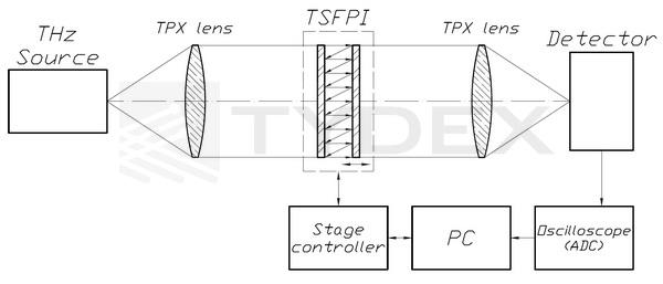
Fig. 1. Principal diagram of TSFPI.
TSFPI may be used with the following sources:
- Gyrotrons;
- Optically pumped submillimeter wave lasers;
- Backward wave oscillators;
- Free-electron lasers;
- Difference-frequency THz generators;
- Photomixing THz generators;
- Quantum cascade lasers;
- p-Ge lasers;
- Novel THz sources.
THz Scanning Fabry-Perot Interferometer is also capable of measuring wavelength and intensity of wideband THz sources, as well as filtering THz radiation as per Fabry-Perot interferometer transmission spectrum (fig. 2).
TSFPI supports many mirror translation modes, such as moving the mirror into a given position, shifting the mirror for a given distance, continuous and cyclic translation. Mirror translation speed, interval between shifts, starting and ending positions can be adjusted as well.
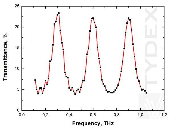
Fig. 2. TSFPI transmission spectrum at 500 μm spacing between mirrors as measured by TDS spectrometer Menlo Systems TERA K8.
Fig. 3 shows the result of the measurement of lasing wavelength of optically pumped sumbillimeter wave laser performed by TSFPI. As can be seen in the diagram, distance between adjacent TSFPI transmission maxima is about 216 μm (433 μm – 216 μm = 217 μm; 647 μm – 433 μm = 214 μm; 865 μm – 647 μm = 218 μm), which corresponds to half the wavelength of the laser. This result agrees with theoretical TSFPI transmittance maxima: λ=2*d/m, where d is the spacing between TSFPI mirrors in μm, m is the interference order, λ is the wavelength being measured in μm.
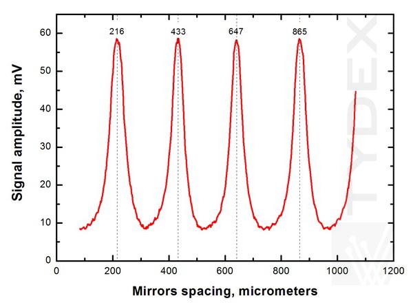
Fig. 3. Signal amplitude at optoacoustic detector Tydex GP-1P vs TSFPI mirror spacing. THz radiation is generated by an optically pumped submillimeter wave laser, λlas = 432 μm.
Key TSFPI specifications are summarized in Table.
| Specification | TSFPI-1 | TSFPI-2 | TSFPI-RF-1 | TSFPI-RF-2 |
| Operational frequency range, THz | 0.1 - 15 | 0.02 - 15 | ||
| Free spectral range, THz | 0.01 - 1.8 | |||
| Spacing between mirrors, mm | 0 - 9.5 | 0 - 29.5 | ||
| Spacing setting accuracy, μm | ± 1.25 | |||
| Optical axis height, mm | 53 | 110 | 53 | 110 |
| Free aperture, mm | 26 | 52 | 26 | 52 |
| Dimensions (LxHxW), mm | 150х90х112 | 232х151х120 | 170x90x112 | 232х151х120 |
| Mass, kg | 2.3 | 2.5 | 2.4 | 2.7 |
Key features:
- Wide operating range of the device;
- High breakdown threshold;
- Large aperture: up to 52 mm;
- High accuracy of mirror positioning: ±1.25 μm
- Easy-to-use.
TSFPI package includes the following:
- TSFPI interferometer unit;
- Power supply and control unit;
- Mirror translation control software;
- Cables;
- User guide.
Following accessories for the TSFPI can be supplied separately:
- Optoacoustic Golay Detector GC-1P/T/D;
- BPF (band-pass filters) for a specified wavelength within 0.1-15 THz range;
- LPF (low pass filters) to filter out IR radiation, with the following cut-off frequencies: 23.4 THz, 23.3 THz, 23.1 THz, 14.3 THz, 10.9 THz, 8.8 THz, 5.5 THz, 4.3 THz, 4 THz, 3.2 THz;
- A set of attenuators with 1%, 3%, 10% and 30% transmittance;
- TPX and HRFZ-Si lenses.
For price quotation and delivery please fill in our Request form.
Optics is ready to be shipped!
Optics Stock
Shipment/ Payment/ Warranty ...

