FTIR Beam Splitter
| Download FTIR Beam Splitter Datasheet (PDF, 221 KB) |
Application and principle of operation
Beamsplitter / compensator set is used in Michelson interferometer scheme in Fourier transform infrared (FTIR) spectrometers.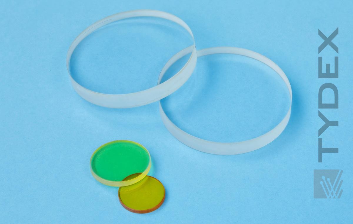
FTIR spectrometer is generally based on Michelson interferometer where one of the mirrors is movable. Two mirrors are located at both arms of interferometer and oriented perpendicularly to each other. Beamsplitter is placed at the vertex of the right angle and oriented at a 45° angle relative to each mirror. Light passing to the beamsplitter is divided into two parts (50%/50% ideally) those propagate further to the both arms and are reflected off the mirrors. The beam which is one time reflected from the beamsplitter (upper beam on the drawing) must also pass there and back through an inclined compensator plate to compensate for the fact that the other beam passes through the beamsplitter plate three times instead of one. The movable mirror is scanned over some distance that produces an interference pattern of the two beams reaching the detector. Fourier transform of the signal encodes the spectrum of a source (investigated material).
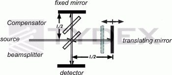
as a part of FTIR spectrometer.
The wavelength range from visible to Far IR can be covered by choosing the appropriate material of beamsplitter and compensator.
The material choice includes the following materials: fused silica (quartz) (Visible/Near-IR), CaF2, BaF2, and ZnSe (Near-IR/Mid-IR).
High Resistivity FZ-Silicon could also be recommended for beamsplitters in Far IR region. Due to Fresnel reflection it can be used for ~50%/50% beam splitting in very wide wavelength range without any coating.
Tab. 1 Typical operational wavelength ranges for beamsplitter vs. material.
| Visible-IR Fused Silica | 0.4-1.1 µm (25,000-9,000 cm-1) or 0.65-3.0 µm (15,000-3,300 cm-1) |
| CaF2 | 0.65-8.5 µm (15,000-1,200 cm-1) |
| BaF2 | 0.65-12 µm (15,000-850 cm-1) |
| ZnSe | 2-14 µm (5,000-750 cm-1) |
| HRFZ-Si | 50-1000 µm (200-10 cm-1) |
Specification and tolerances
In order to achieve high resolution of the FTIR spectrometer the beamsplitter/compensator pairs should be produced with very high degree of accuracy. Particularly surface flatness, wedge tolerance, and thickness matching are together of great importance.
Tab. 2 Achievable specification.
| Diameter, mm | to 100 |
| Surface flatness, λ at 633 nm | to 1/10 |
| Wedge tolerance, arc sec | to +/-10 |
| Thickness matching, µm | to 1 |
N.B. The best possible specification depends on material and parameters combination.
Coatings
For the alignment purposes the combined pattern of the coatings can be applied on the surfaces of FTIR beamsplitter/compensator. The “windows” for visible beam – visible regions of a special shape depending on dimensional design of interferometer are placed together with IR-regions. Typical coating pattern looks like the one below.

| Part | Region | Coating type | Reflection/Transmission |
| Beamsplitter | A | Partial reflecting | R/T=50%/50% @ 633 nm |
| B | Partial reflecting | R/T=(50/50+/-10)% @ 7-14 µm or R/T=(50/50+/-20)% @ 2.5-14 µm |
|
| C | AR | R <0. 5% @ 633 nm | |
| D | BBAR | Rave<4% @ 7-14 µm or Rave<5% @ 2.5-14 µm |
|
| Compensator | A | AR | R <0. 5% @ 633 nm |
| B | BBAR | Rave<4% @ 7-14 µm or Rave<5% @ 2.5-14 µm |
|
| C | AR | R <0. 5% @ 633 nm | |
| D | BBAR | Rave<4% @ 7-14 µm or Rave<5% @ 2.5-14 µm |
Fig. 2 and Tab .3 Coating pattern of ZnSe beamsplitter/compensator pair (example).
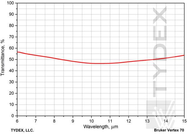
Fig. 3.1. Transmission plot of beamsplitter (T=(50+/10)%@8-14 µm).
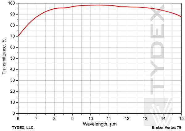
Fig. 3.2. Transmission plot of compensator (AR@8-14 µm).
Other coating patterns and coating types are available upon request.
Tydex has long-time experience of supplying the beam splitter / compensator pairs (substrates without coatings and coated finished parts) for FTIR spectroscopy to the customers in Europe, USA, and Far East.
For quotation and delivery please fill in our request form.
Optics is ready to be shipped!
Optics Stock
Shipment/ Payment/ Warranty ...

