IR Coatings
| Download Optical Coatings Datasheet (PDF, 7 MB) |
Quarter-wave films used as IR coatings are 10 to 20 times thicker than those for visible region. Therefore, levels of stress and absorption, while negligible in the visible region, become limiting factors in the design of the IR coatings. Most oxides exhibit too high absorbance in the IR spectral region, and MgF2 produces films with exceeding levels of physical stress. Besides that IR substrates usually have high refraction indices. Therefore, high-performance film-forming materials are required to produce efficient interference structures. "Visible" materials can not be used as the main ones for the formation of optical IR coatings.
The main film-forming materials for the IR range are fluorides, chalcogenides and semiconductors. These materials tend to have significantly worse mechanical and climatic stability parameters than oxides and MgF2, as well as poorly tolerated ion assisting. To improve the performance of coatings, in many cases it is necessary to introduce additional functional layers and interlayers and to seek a compromise between strength, efficiency and damage threhold.
1. Simple IR Coatings
2. Broadband IR Coatings
3. Super Broadband IR Coatings
4. IR Mirrors
5. Beam Splitters
6. Beam Splitter Coatings for Fourier
1. Simple IR Coatings
1.1. Single-layer Quarter-wave AR Coatings
The key advantage of quarter-wave films is the fact that even outside the zone of enlightenment they do not degrade the transmission of the part. The maximum bleaching is achieved when the refractive index of the bleached material and the film deposited are correctly matched. A classic film of magnesium fluoride, even if it could be applied with the required thickness for IR, would not provide an effective antireflection effect on IR substrates because of its too low refractive index. However, some analogs of a single layer can be made for the IR range. For example, a single-layer film of zinc sulphide on germanium is a sufficiently effective antireflection coating, and inferiority is the second only to a diamond-like coating.
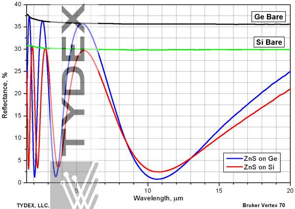
Fig. 1.1.А. Reflection from silicon and germanium surfaces treated with ZnS film, as compared to reflection from bare surfaces.
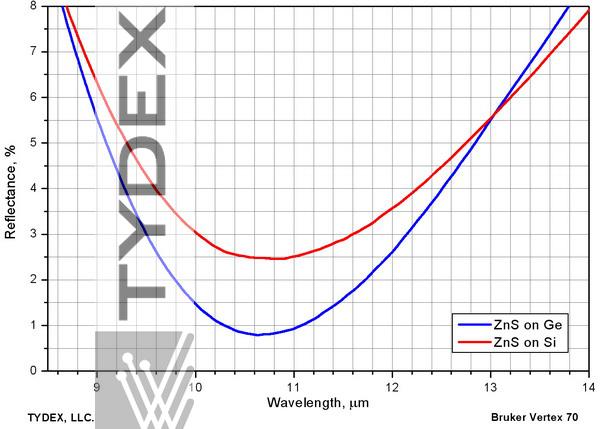
Fig. 1.1.В. ZnS film on silicon and germanium surfaces. Maximum antireflection efficiency zone.
One can see the refractive index of the film is nearly perfect for germanium, but somewhat too high for silicon. Lead fluoride has high spectral efficiency when used as a single-layer antireflection coating on silicon. 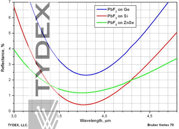
The film has nearly perfect refractive index for silicon. The reflection at the minimum does not exceed 0.5%. The film also has good anti-reflection properties on zinc selenide. Its refractive index is too low for germanium.
1.2. Waterproof Coating on Salts
A variant of a single-layer IR coating can be considered a protective coating on potassium bromide and other salt crystals (NaCl, KCl, etc.). Low refractive index of salts and their wide range of transparency make it practically impossible to improve their optical properties by film deposition. To protect optical components made of salt crystals, an inorganic film is applied to their surface. This film is thin enough for all interference effects to remain in the short-wave inoperative region.
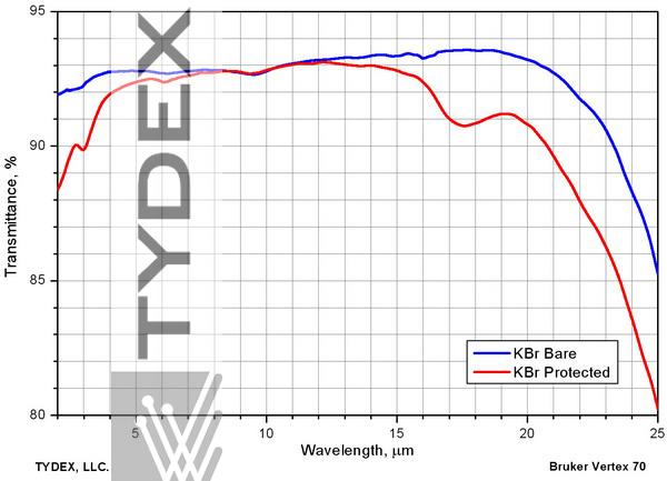
Fig. 1.2. KBr window transmission bare and protected. The transmittance is marginally lower, no “organic” absorption bands are introduced.
1.3. V-type AR Coating for a Single Wavelength
Like their counterparts for the visible spectral range, V-type antireflection coatings are based on a design of two films with high and low refractive index. As for visible structures, varying the thicknesses and refractive indices of the layers, it is possible to optimize the design for a given substrate, the wavelength, and the angle of incidence of light. As in the "visible" case, the reflection from this structure outside the narrow operating range will be higher than from the surface without coverage. Usually these such structures are used for clarification at laser wavelengths or at working wavelengths of gas analyzers.
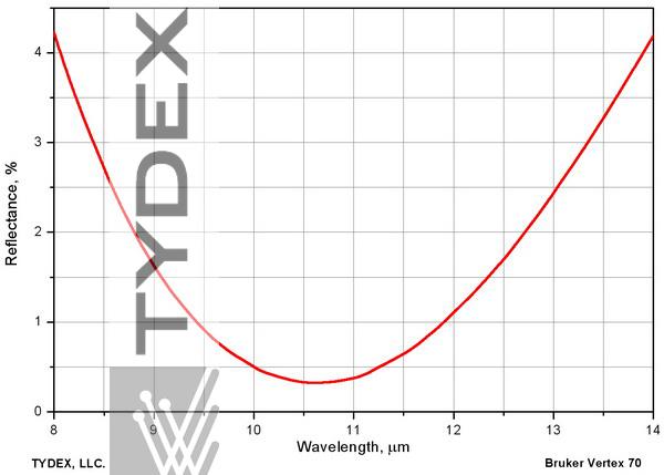
Fig. 1.3. AR coating on zinc selenide at 10.6 μm (used with CO2 laser).
1.4. AR Coating for Er:YAG @ 2.94 μm
A particular case of a V-type anti-reflection coating is coating for Er:YAG lasing @ 2.94 μm. This wavelength coincides with the peak of absorption of water, which is almost always present within the pores of oxide structures. By using hydrophobic IR materials, it is possible to produce a structure with lower absorption than a V-type oxide coating for the same wavelength.
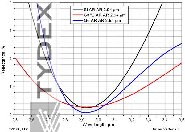
Fig. 1.4. AR coating at 2.94 μm on germanium, silicon and calcium fluoride.
2. Broadband IR Coatings
2.1. Broadband AR Coating for 3-5 μm Range
One of the most widely used spectral ranges is the so-called “first atmospheric window” between 3 and 5 μm. It is sometimes narrowed to 3.7-4.8 μm. A lot of optical materials, such as silicon, zinc selenide, germanium, fluorite, sapphire and IR quartz are used at these wavelengths. For all these materials Tydex offers high-performance broadband coating, which has sufficient resistance to working outdoors under non-extreme conditions. Multilayer structures are used, containing no less than three materials with different refractive indices.
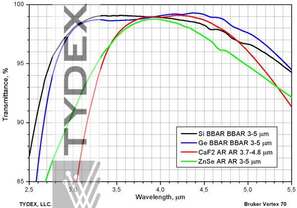
Fig. 2.1.А. Broadband AR coating for the first atmospheric window applied to key IR materials.
On silicon and germanium this coating can be combined with DLC on the front surface of the product. For more details refer to the article about DLC (Diamond-like Coating).
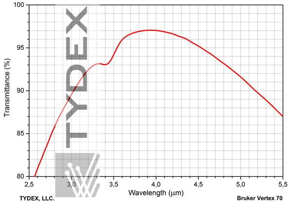
Fig. 2.1.В. Transmission of a silicon window. Diamond-like coating on the front side, broadband AR coating on the back side.
2.2. Broadband AR Coating for 7-14 μm Range
In the second atmospheric window, 7-14 microns, germanium and zinc selenide are used as a material for manufacturing optics. In some cases silicon can be used. For this range we propose constructively the same design of AR coatings as for 3-5 μm, but the thickness of the interference layers becomes approximately 2.5 times larger. It makes the coatings somewhat less resistant and requiring for more accurate handling. Higher performance parameters can be achieved by dropping some of the spectral efficiency. After 11 μm the substrates and the sputtered structures show appreciable absorption.
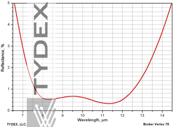
Fig. 2.2.A. Residual reflection of Ge plate with two-side AR coating for 7-14 μm range.
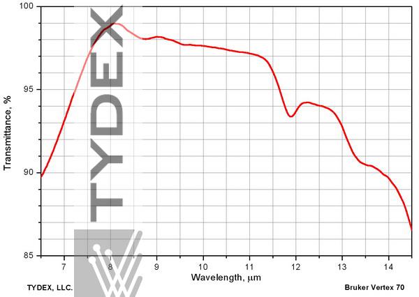
Fig. 2.2.B. Transmitssion of Ge plate with two-side AR coating for 7-14 μm range.
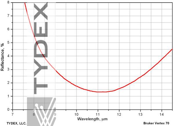
Fig. 2.2.C. Residual reflection of ZnSe plate with two-side AR coating for 7-14 μm range.
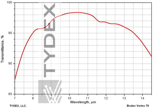
Fig. 2.2.D. Transmission of ZnSe plate with two-side AR coating for 7-14 μm range.
Similarly to the case of the first atmospheric window, when used on silicon and germanium, this coating can be combined with DLC on the front side of the component.
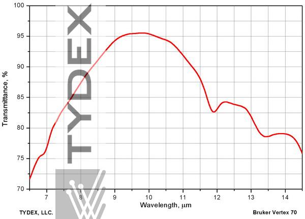
Fig. 2.2.E. Transmission of Ge plate with DLC on the front side, 7-14 μm AR coating on the back side.
2.3. Broadband AR Coating for 3-5 + 8-12 μm Range
In some cases both infrared bands are channeled by a common optical system. For these cases we offer enlightenment in both ranges. Since it is impossible to clear both these channels simultaneously by a single layer, the use of resistant DLC or ZnS for the front surface is excluded. We have developed and manufactured wide-band illumination for both ranges for germanium substrates, which has an acceptable resistance to outdoor operation under non-extreme conditions.
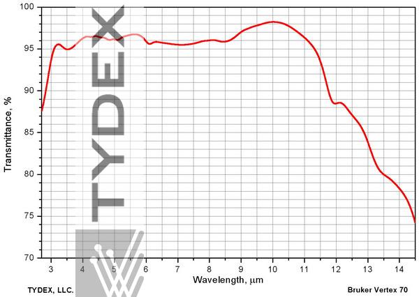
Fig. 2.3. 3-5 and 8-12 μm antireflection coating on germanium.
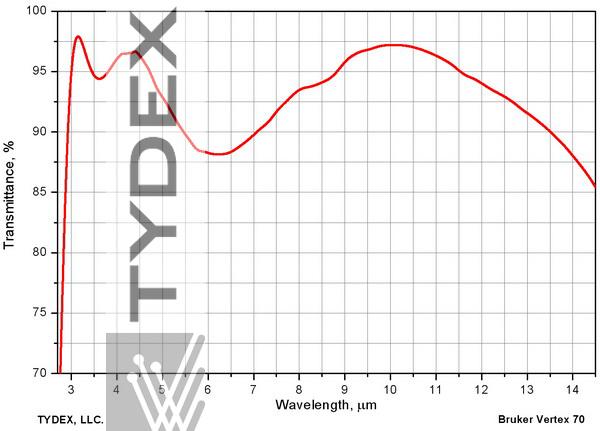
Fig. 2.3.А. 3-5 and 8-12 μm antireflection coating for zinc selenide.
3. Super Broadband IR Coatings
3.1. Broadband AR Coating for 1.6-15 μm Range
Optical components of Fourier spectrometers must provide the widest possible transparency range. The most widely used material for such components, besides salts, is zinc selenide. We have developed and regularly produced an antireflection coating for this material which improves the transmission of products in the range from 1.6 to 15 μm.
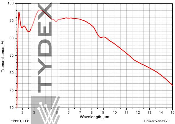
Fig. 3.1. Transmission of a ZnSe window with two-side broadband ARcoating for 1.6-15 μm range.
If it is desirable for the customer to attenuate the visible and near-IR radiation to eliminate unwanted light. We offer a "dark" AR coating, effectively suppressing the undesirable range.
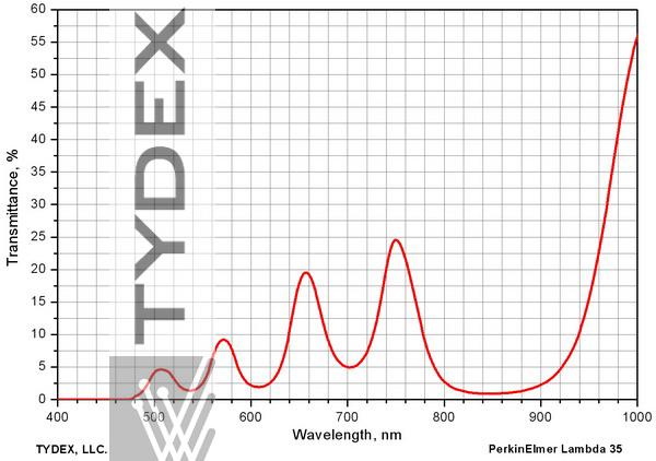
Fig. 3.1.А. Visible and near IR transmission of a “dark” AR coating for 1.6-14 μm range.
3.2. Super Broadband AR Coating for Germanium and 2.5-25 μm Range
Elements of high refractive materials are needed for ATR spectroscopy . The Fresnel losses at the input to such an ATR element and at the output from it substantially weaken the signal. There is a need to reduce the Fresnel losses in the widest possible spectral range. We have developed and produced this AR coating for germanium ATR probes.
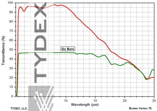
Fig. 3.2. Transmission of a Ge probe with AR coating as compared to a bare component.
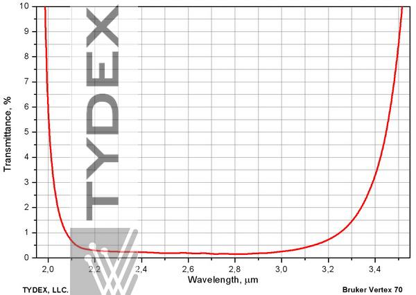
Fig. 4.1.А. Interference mirror for 2.1-3.3 μm range on ZnSe substrate.
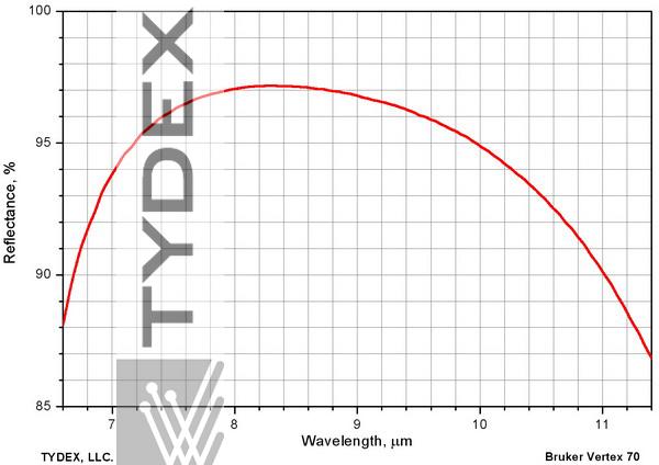
Fig. 4.1.В. Interference mirror for 7-11 μm range on Si substrate, angle of incidence 45°.
4.3. Solar-blind Coatings
Another important application of interference IR mirrors is NIR cutoff. This problem arises, for example, when producing pyrgeometers - instruments for measuring the temperature of the earth's surface. For conducting correct measurements it is necessary to cut out direct sunlight from the thermal radiation of the earth's surface. Sunlight is energetically concentrated mainly in the range 0.2 - 5 microns. For the reradiated energy, the intensity peak is in the region of 15 μm (depending on the temperature), and it is important to pass the radiation to 45-50 μm. The exact cut-off wavelength can vary somewhat depending on the design features and the use of the finished product. It is selected in the range 4.5-5.5 μm. A family of the coatings, cutting light to the left of 5 microns and passing through 5-45 microns, was called the solar blind (filter-cutting) filters.
Specification:
|
Coating sandwich
|
Wavelength range 6-15 µm
|
Wavelength range 18-40 µm
|
| DLC +Si substrate +solar blind | Taverage>= 70% Tpeak= 85-90% Tmin= 60% |
Taverage>= 50% Tpeak= 55-60% Tmin= 35-40% |
| Si substrate + solar blind (without DLC) |
Taverage>= 55%
Tpeak= 60-70% Tmin= 50% |
Taverage>= 45% Tpeak= 50-55% Tmin= 35-40% |
| Additional specification to both coating sandwiches | ||
|
Working temperature range
|
-40 deg. C ...+80 deg. C | |
|
Humidity
|
relatively high, up to 90-95%
|
|
|
Cut-off wavelength
(to be specified additionally) |
4.4 +/- 0.3 µm
|
|
| Tpeak (not more than 2 peaks) at the range before cut-off |
<=0.4% (in the range 1-4.5µm) | |
| The range where transmission exceeds 20% |
up to 45 µm | |
Similarly to usual “cold” dielectric mirrors, a solar blind coating is designed as an interference mirror with several additional layers enhancing its spectral characteristics in the long-wavelength area. Most of the film-forming IR materials show significant absorption above 12-15 μm. To ensure high transmission in the long-wave zone up to 45 μm, only suitable materials should be used in the design.
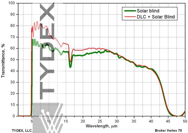
Fig. 4.3. Transmission of Si sample with a single-side Solar Blind coating and two-side Solar Blind + DLC coatings.
These filter coatings are widely used in pyrgeometers, instruments that measure effective radiation of the earth’s surface.
Our meniscal lenses with solar blind coating have been successfully tested as a part of a pyrgeometer by the Physical-meteorological observatory at Davos, Switzerland.
An interference structure can be used to increase the reflection of a surface in a wide spectral range while retaining partial transparency in the same range, i. e. to split the light beam between reflection and transmission. We have mastered the production of such parts based on semi-reflecting non-metallic interference structures.
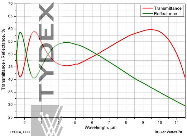
Fig. 5. 50/50 beam splitter on a barium fluoride substrate.
6. Beam Splitter Coatings for Fourier
The dividers for the Fourier spectrometers should not only divide the IR spectrum, but also have a division zone of the calibration laser it is 633 nm. For more detailed information please refer to the article Substrates for the FTIR Beam Splitters.
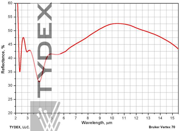
Fig. 6.А. An example of a splitter coating on ZnSe substrate. Angle of incidence 45°.
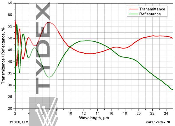
Fig. 6.В. An example of a splitter coating on KBr substrate. Angle of incidence 30°.
Optics is ready to be shipped!
Optics Stock
Shipment/ Payment/ Warranty ...

