Optical Coatings for Visible and Near IR Spectral Range
| Download Optical Coatings Datasheet (PDF, 7 MB) |
Oxides and magnesium fluoride are the materials for optical coatings in this range. They form dense, durable films that are resistant to mechanical and climatic influences, with extremely low absorption and low scattering. Therefore, coatings for this spectral range show high operational and radiation resistance. The use of ion assisting gives an additional benefit in the stability of the resulting structures.
Our coatings are not limited to a standard set of designs. On the contrary, we try our best to satisfy the customer's requirements. Please contact us and we will do our best to solve your problem as fully as possible.
1. Antireflection Coatings
2. Dielectric Mirrors
3. Beamsplitter Coatings
1. Antireflection (AR) Coatings
1.1. MgF2 Quarter-wave AR Coating
The simplest interference antireflection coating seems to consist of a single layer of magnesium fluoride (MgF2). As MgF2 film has a very low refractive index (approximately 1.38 at 550 nm), depositing a quarter-wave film on any optical glass can significantly reduce the residual reflection. So, for K8 (refractive index 1.52) - from 4.1% to 1.2%. On high refractive glasses and sapphire, the effect of this film is even higher, the reflection at the central wavelength drops below 0.5% at 7-9% reflection from the uncoated product. To the left and to the right of the central wavelength, the reflection gradually grows, remaining in the entire spectrum lower than the reflection from the detail without coverage. So, the 550 nm-centered film provides acceptable clarity in the entire visible range. For K8 glass, the integral reflection loss at 400-800 nm decreases approximately twice on each surface, for high-refractive glasses - by 10 times.
An important advantage of this coating is the highest in its class mechanical and chemical resistance.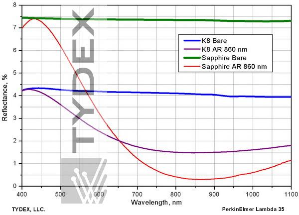
Fig. 1.1. Comparison of reflectance of bare K8 and sapphire surfaces to MgF2-coated ones.
1.2. V-type AR Coating for a Specific Wavelength
The designation "V-type" comes from the V-shaped form of the residual reflection curve (as opposed to the MgF2 film, when the reflection curve looks like a very flat "U"). V-type AR coatings typically consist of two non-equally thick layers of oxides with high and low refractive index. Varying the thicknesses and refractive indices of the layers, it is possible to achieve extremely low losses at a given wavelength. Typically, such coatings are designed for laser generation lines. The design is optimized for the operating angle of incidence of light.
The standard value of the residual reflection from each surface for the V-coat is less than 0.25%. Reaching a value of ≤0.15% is also possible on special request.
Unlike the single-layer clearing of MgF2, this structure can be optimized to produce this reflection on glasses of virtually all brands and most crystals.
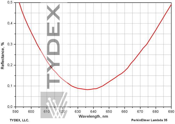
Fig. 1.2.A. Residual reflectance of a K8 part with a V-type antireflection coating at 633 nm, normal incidence angle.
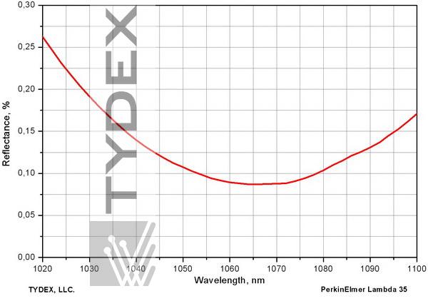
Fig. 1.2.B. Residual reflectance of a K8 part with a V-type antireflection coating at 1064 nm, normal incidence angle.
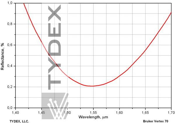
Fig. 1.2.C. Residual reflectance of a K8 part with a V-type antireflection coating at 1550 nm, normal incidence angle.
However, it should be remembered outside the narrow operating range the reflection from this structure will be higher than from the uncoated surface.
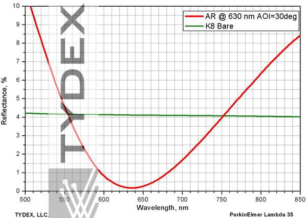
Fig. 1.2.D. Reflection from a component with a V-type antireflection coating compared to reflection from bare K8. Angle of incidence 30°, polarization (s+p)/2.
1.3. Dual-band W-type AR Coatings
Two-way AR multilayer coatings are required when the optical components must provide very high transmittance at two different wavelengths. For example, when it is necessary to ensure that the fundamental wavelength of the laser generation and the second harmonic pass through the optical element. The presence of two "dips" in the spectrum of residual reflection of this coating makes it look like the letter W, which gives the name to this family of coatings. Structurally these coatings consist of 4 layers formed by three materials with different refractive indices.
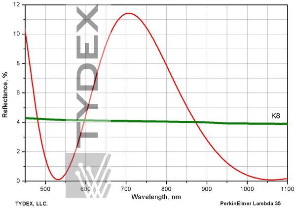
Fig. 1.3.А. Residual reflectance of a K8 surface with a W-type AR coating at 1064 and 532 nm,
angle of incidence 0°.
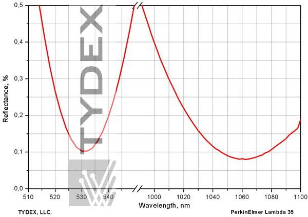
Fig. 1.3.В. W-type AR coating for 532 and 1064 nm, angle of incidence 0°.
1.4. Broadband Antireflection (BBAR) Coating
Low reflection in a wide spectral range is achieved by using the structures of three to six layers consisted usually of three or more materials with different refractive indices.
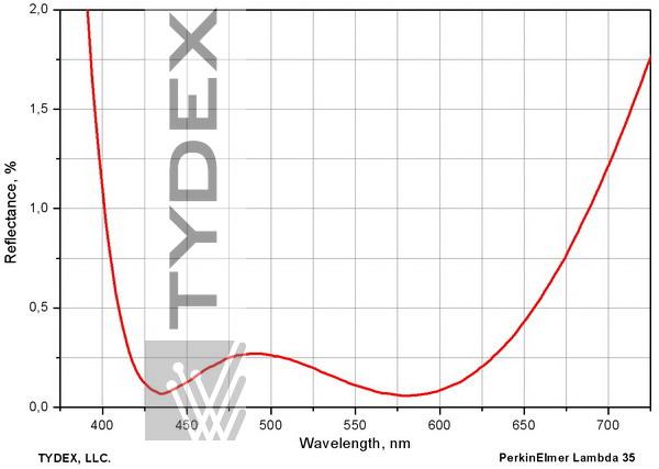
Fig. 1.4.A. Residual reflectance of a TF-9 part with a broadband AR coating for 400-700 nm range, normal angle of incidence.
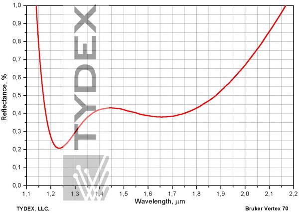
Fig. 1.4.B. Residual reflectance of a K8 part with a broadband AR coating for 1.2-2 μm range, angle of incidence 45°, (s+p)/2.
2.1. Dielectric Mirrors
High reflective (mirror) coatings consist of a sufficient number of pairs of equal-thickness layers of dielectric materials. The thickness of the layers and the number of pairs are determined on the basis of the condition for obtaining the required reflection at the central working wavelength and at the working angle of incidence. The width of the reflection zone is determined by the ratio of the refractive indices of the dielectrics used and is about 10-12% of the working wavelength. Such mirrors are created for working with lasers, when high reflection at one wavelength and high radiation resistance are required. Reflection from such structures in the working range exceeds 99% (typical for metals does not exceed 95%), and the radiation resistance is several Joules per cm2 (vs. 0.3 J/cm2 for metals). These coatings are usually designed for a 0 or 45 degree angle of incidence, but can be optimized for almost any other angle. For example, for our off-axis parabolic mirrors, dielectric designs are optimized for an operating angle of incidence equal to half the off-axis angle of the parabola.
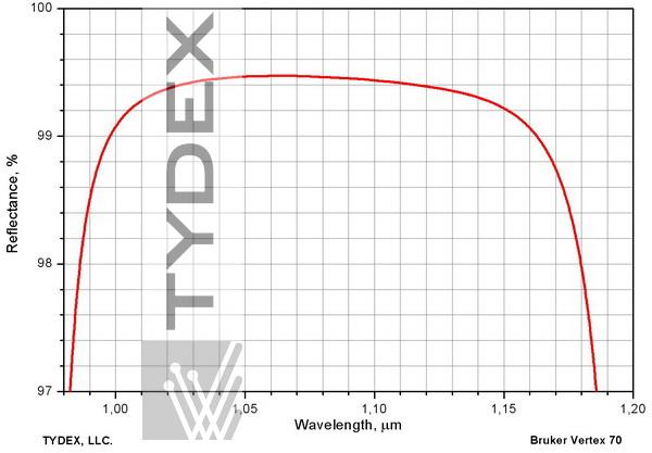
Fig. 2.1.A. Highly reflective dielectric mirror, 1064 nm, angle of incidence 0°.
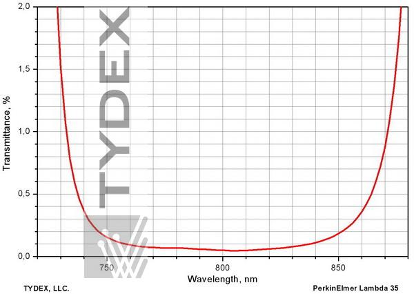
Fig. 2.1.B. Dielectric mirror for 750-850 nm range, angle of incidence 22.5°. Residual transmitssion is shown. Polarization (s+p)/2.
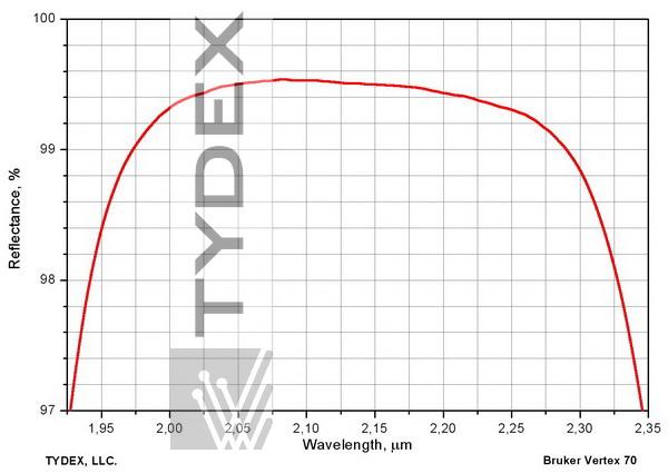
Fig. 2.1.C. Dielectric mirror for 2.1 μm wavelength, angle of incidence 45°, (s+p)/2.
2.2. Dual-band Highly Reflective Coating
The design obtained as a result of successive deposition of two dielectric mirrors on the same substrate will have a high reflection at two wavelengths, although its radiation resistance will noticeably decrease. These mirrors are convenient to use when the system uses two lasers or a laser and its harmonic. A typical problem is channeling the sewage of the 1064-nm working beam and the 633-nm pilot imaging beam.

Fig. 2.2. Dual wavelength high-reflective mirror.
See also the section Metal-dielectric Mirrors.
2.3. Broadband Highly-reflective Coatings
Sputtering on one substrate two dielectric mirrors centered on two close wavelengths, it is possible to obtain a product with a broad, even reflection spectrum. These coatings are in demand for working with tunable lasers (for example, Ti: Sa), especially at high angles of incidence, as well as for products that provide high reflection in a wide range of working angles.
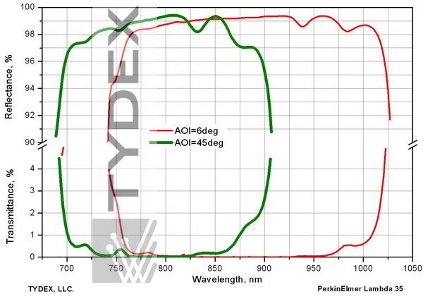
Fig. 2.3. Highly reflective “double” mirror for 700-900 nm range, angle of incidence 45°, (s+p)/2.
Also shown the spectrum of the same mirror at normal incidence.
Metal and metal-dielectric broadband highly-reflective coatings are used as well.
Broadband highly-reflective coatings may also be metal, metal-dielectric.
3. Beamsplitter Coatings
3.1. "Cold/Hot" mirrors and cut-off filters
Besides the main reflection zone, the classical dielectric mirror has side maxima that are on the spectrum both to the left and to the right of the working wavelength.
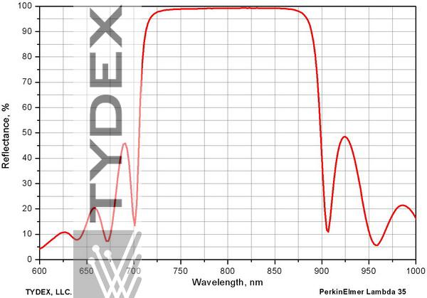
Fig. 3.1.А. Dielectric mirror and side peaks of reflection
By varying some layers of the "classical" packet, we can, without changing the reflection in the working spectral region, redistribute these side maxima, suppressing them either in the shortwave or in the long wave region. This way, it is possible to provide a sufficiently high transmission in the region to the left or right of the main mirror region. Depending on the side where the side peak was suppressed, these structures are called either cold or hot mirrors. "Hot" mirrors reflect infrared radiation, letting the visible. Such mirrors are used in projection systems to reduce the thermal load.
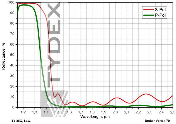
Fig. 3.1.В. A “cold” mirror. Reflection range 1.15-1.35 μm, S-pol, transmittance range 1.5-2.5 μm, P-pol. On KI quartz substrate, angle of incidence 45°
The same construction can be used to create a cutoff filter and protect a photodetector from unwanted radiation.
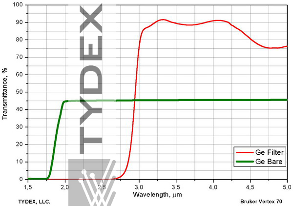
Fig. 3.1.С. Cutoff filter. Transmission over 85% within 3.25-3.75 μm range (second side with AR coating). Transmission less than 0.1% below 2.5 μm. Germanium substrate. A spectrum of bare germanium is provided for comparison.
3.2. Beamsplitting and Combining Designs
They are similar to "cold/hot" mirrors and allow to reduce the lasers beams at different wavelengths.

3.3. Polarization Splitters
At non-zero angles of incidence, S-polarized light is reflected much more effectively than P-polarized light. Also the high-reflection zone for P-polarized light gets narrower much faster than for S-polarized light. This effect allows creation of mirrors that strongly reflect S-polarized and transmit P-polarized radiation.
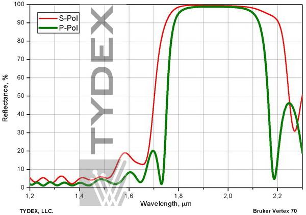
Fig. 3.3. Polarization splitter. High reflection at 2.05 μm, s-pol, high transmissivity at 2.2 μm, p-pol. Angle of incidence 50°
3.4. Laser Output Mirrors
It is necessary to spray a sufficient number of films pairs with high and low refractive indices to get a dielectric totally reflector. With a smaller number of pairs, the reflection will be lower, but a part of the light will pass through the mirror. These designs practically do not absorb light, and the losses for scattering in them are minimal. Selecting the number of pairs, as well as the thickness and material of the last layer, one can achieve almost any ratio of transmission and reflection. These designs are ideally suited to work as output mirrors in laser cavities, removing the maximum possible power from the resonator and supporting a standing wave in it.
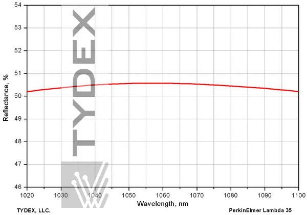
Fig. 3.4. Beam splitting coating R=(50 ±1)% at 1064 nm, angle of incidence 0°
3.5. Broadband Semi-reflective (Beamsplitting) Coatings
Partially-reflective coatings for broadband applications are made in the same way. A typical application is a beam divider that directs part of the light from the object to the eyepiece, and the rest of the energy to the photodetector. Another example is the energy divider in the white light interferometer.
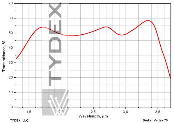
Fig. 3.5. Beam splitting coating for 1.5-3.5 μm range (s+p)/2, 45° AOI. KI quartz substrate
3.6. THz splitters
Dielectric mirrors can be used to solve the problem of separating the generated THz radiation and residual radiation from a Ti-sapphire pump laser. This mirror should consist of transparent materials in the THz range deposited on a substrate transparent in teraherts (usually silicon or crystalline quartz). Read more in the THz Spectral Splitters section.
Optics is ready to be shipped!
Optics Stock
Shipment/ Payment/ Warranty ...

